Stereo Vision
Contents
Introduction to Dense Stereo Vision
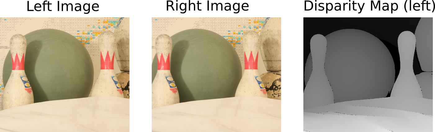
Dense Stereo Vision takes two input images, left and right, which are shifted and matched to generate the depth of each pixel. The two terms, "depth map" and "disparity map", are often used interchangeably.
The pseudo code below provides an over view of a simple disparity map algorithm.
Create a "minSSD" array equal to the size of the image, with large initial values.
Create a "disparity" array equal to the size of the image.

for k = 0 to MAX_SHIFT do
    Step 1: Shift right image to the right by k pixels
    Step 2: Perform Sum of Squared Differences (SSD) between left image and shifted right image
    Step 3: Update the minSSD and disparity array.
            for each pixel coordinate (i,j) do
                if ssd(i,j) < minSSD(i,j) do
                    minSSD(i,j) <= ssd(i,j)
                    disparity(i,j) <= k
                end
            end
end
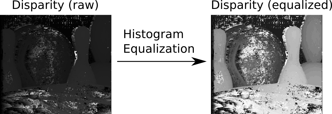
To visualize the depth map generated by the above algorithm, histogram equalization is performed to enhance the contrast of the depth value.
The details of disparity map and histogram equalization are described in the following subsections.
Disparity Map
Padding and Shifting the Images
The images are padded with a "frame" of zero pixels to facilitate the window operation (SSD/SAD) at the boarder. In the CPU code, the width of the margin, or "frame", is set to half of the width/height of the window operation. In the GPU code, you may pad images with larger margins to match the size of the thread blocks.
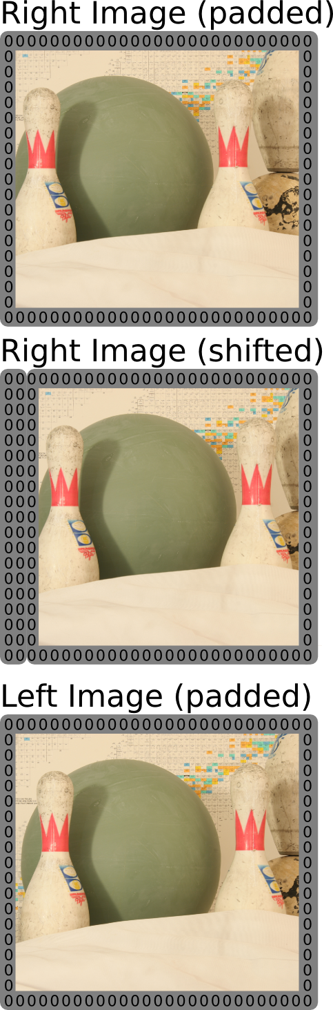
Compute Sum of Squared Differences (SSD) or Sum of Absolute Differences (SAD)
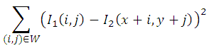
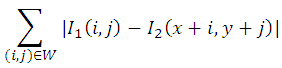
This is a dense operation on each pixel of the right image (shifted) and left image (padded). The SSD operation on pixel (x,y) over a window W is shown by the formula below:
The SAD operation on pixel (x,y) over a window W is shown by the formula below:
In the CPU implementation, the SSD is separated into two steps:
- Perform the squared differences or absolute differences of each pixel.
- Sum the squared differences or absolute differences over a window W.
Update Disparity Map
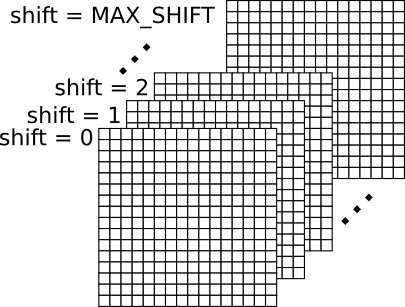
For each shift value of the right image, there is an SSD/SAD map equal to the size of the image. It leads to a 3D space, which contains "MAX_SHIFT" number of SSD/SAD maps, as shown in the figure below.
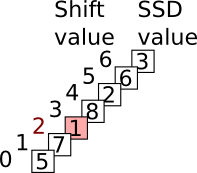
The disparity map is a 2D map reduced from the 3D space above. The disparity of a pixel is equal to the shift value that leads to minimum SSD/SAD for that pixel. The figure below shows an example of different SSD values of a single pixel at different shifted values. The disparity of this pixel is equal to 2, because at shift value 2 this pixel has the minimum SSD value.
The 3D space is an conceptual space. In the implementation, it is not necessary to construct such a space, because it takes huge amount of memory. Instead, we can use a 2D space for the bookkeeping of the minimum SSD/SAD value of each pixel and its corresponding shift value, as shown by the pseudo code above.
Histogram Equalization
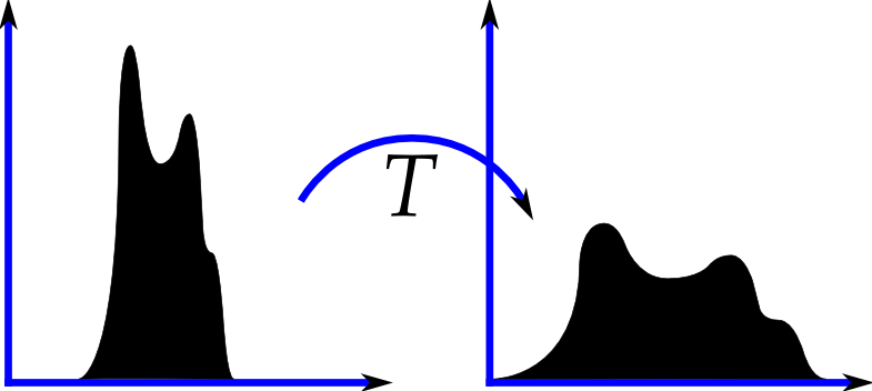
Histogram equalization is a technique often used to enhance the contrast of the image. The Wikipedia entry of histogram equalization provides details of the algorithm, with the figure below showing how histogram equalization transfers the image histogram from left to right.
The histogram equalization contains a few steps:
- Generate the histogram of the image.
- Calculate the cumulative distribution function (cdf) of the histogram
- Compute the transfer function (T), as shown in the figure above, which maps each given gray level to a new gray level.
- Apply the transfer function to each pixel of the input image.
Reference Implementation
We provide a "stereo.zip" package as a reference implementation for CUDA 3.2. It works for both Windows and Linux. You can unzip it to the path of the sample projects of the SDK (for SDK 3.2 it's path_to_cuda_sdk/C/src). The compiled executable should be runned at the same path of the sourse code, or the same path of the Visual C++ project file for Windows. Below is the command to run the executable on the CUDA PC.
cd path_to_cuda_sdk/C/src/stereo
make
./bin/linux/release/stereo
After running the executable, you can get the output image at path_to_cuda_sdk/C/src/stereo/dataset. The pgm images can be viewed using the "eog" command on the CUDA PC. For Windows users, the pgm image can be viewed using "GIMP", which is freely available.
We also provide a "stereoCPU.zip" package, which contains pure C/C++ code. It works for both Windows and Linux. This package is handy for people who want to work on ATI GPU and OpenCL.
Advanced Algorithms and Implementations
There are advanced algorithms and implementations that could provide better error-delay results. Some of them also provide code samples of the implementation. You can study their codes as references. However, you have to write your own code for this assignment.
- Stereo Imaging with CUDA. This articles describes advanced optimization techniques of stereo vision on GPUs, with code samples available from OpenVIDIA.
- A Taxomony and Evaluation of Dense Two-Frame Stereo Correspondence Algorithms. This technical report explains in detail the terminologies and methods of the stereo vision.
- High Performance Stereo Vision Designed for Massively Data Parallel Platforms. This work claims the highest performance of dense stereo vision on GPUs, with code samples available here.
- Comparison of Dense Stereo using CUDA. This paper describes optimization techniques of dense stereo vision on GPUs.